
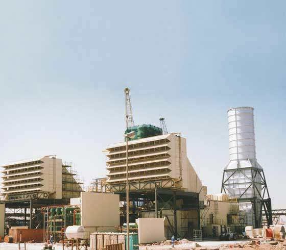
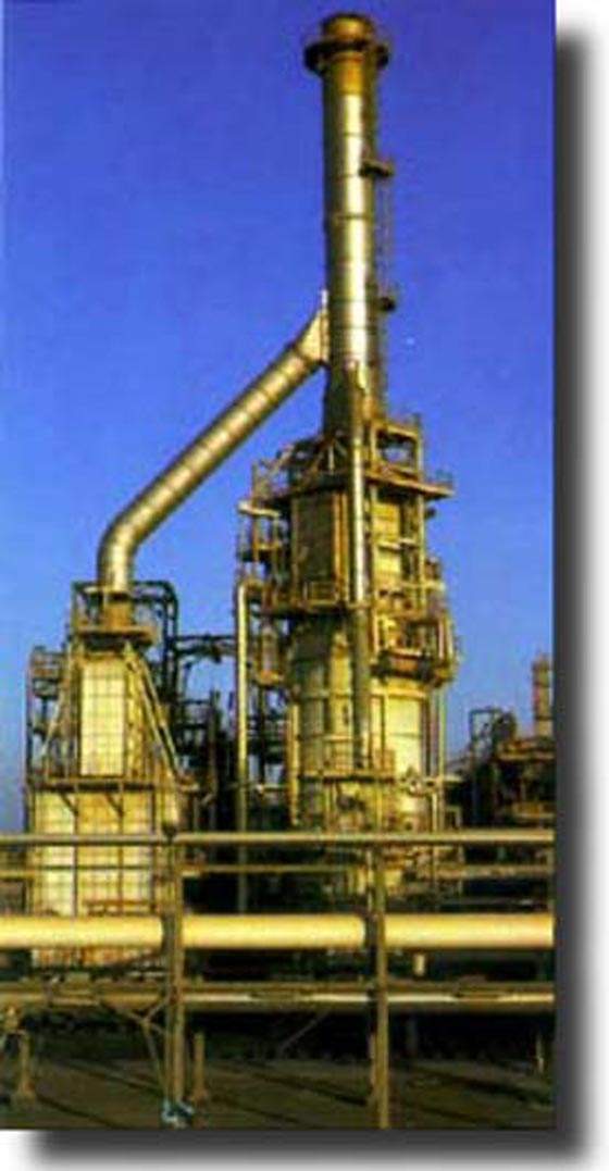
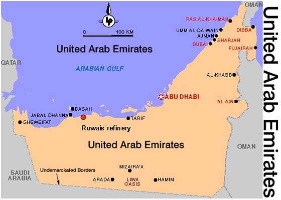
The 500MW cogeneration / desalination plant in Ruwais, United Arab Emirates, brings the plant’s total power capacity to 700MW. The plant forms part of a large industrial complex about 250km west of Abu Dhabi City.
The Ruwais plant will be integrated with one of the UAE’s two refineries, with additions to the refining facility as well as the power generation plant. The owner is Abu Dhabi National Oil Company Ltd (ADNOC), which intends to extend the plant’s refining and petrochemicals capacity as well as its desalination abilities. The desalination plant is needed to supply eight million gallons of water to the refinery each day.
Recommended White Papers
Recommended Buyers Guides
CONTRACTORS AND SUPPLIERS
The order was estimated to cost $600 million, and was awarded to ABB in April 1998. GASCO commissioned the Ruwais upgrade in November 2001.
There is an increasing trend in the Middle East towards local refining and processing, and the Ruwais plant is part of this. As the region is unlikely to supply major equipment locally, it is a key market for European and North American equipment suppliers like ABB despite the widespread trend to production being shifted closer to markets.
ABB SUPPLIES FOUR GAS TURBINES
ABB supplied four GT 13E2 gas turbines with accompanying generators. The turbines are each rated at 160MW (ISO conditions) and have 21-stage subsonic compressors. They also have clean combustion EV burners. The main fuel will be natural gas. Water injection can reduce NOx emissions if the turbine is used with oil.
The turbines will be controlled by ABB’s Egatrol turbine control system (based on Advant). The generators are 210MVA air-cooled devices. ABB will also supply the Heat Recovery Steam Generators (HRSG), the plant control systems, the NOx burners and various ancillary equipment. ABB will also perform the installation and commissioning.
MULTI-STAGE FLASH EVAPORATION FOR DESALINATION
The desalination plant uses multi-stage flash evaporation and the brine is re-circulated and mixed with seawater from the heat reject sections. Heated brine is fed into 12 heat recovery chambers. A fraction flashes to vapour, condenses in condensing tubes and is distilled. The rest of the brine goes to another chamber which has a slightly lower pressure and therefore flashes at a lower temperature.
After the final stage, the brine is mixed with more seawater and reintroduced to the plant at a temperature of 105°C. The desalination plant produces 15,000m³/d. ABB supplied equipment for chlorination, oily water treatment equipment, etc.
GRID CONNECTION USES DOUBLE BUS BAR SYSTEM
ABB Calor Emag supplied parts of the electrical grid of the complex. A 132kV double bus bar system with step up transformers connects to two double bar 33kV and some 11kV systems. The 132kV systems were new gas insulated types, while the rest was a mixture of old and new.
The plant was designed to generate sufficient power even if one of the new generators is switched off. The most important need, however, was grid stability because the network operates as an island.
NCS AND DCS CONTROL SYSTEMS
The plant is controlled by two basic systems, the Net Control System (NCS) and the Distributed Control System (DCS). The system is made more complicated since each turbine has a specific control system which has to interface with the DCS. The main variables in the electrical system are frequency and voltage, which are to be controlled by both primary and secondary control. The primary control is in each machine governor. It adjusts the generated power, when significant frequency upsets occur. The secondary control is in the NCS. The secondary control keeps the frequency modulation of the connected equipment constant.
The DCS has to handle steam head pressures, HRSG drum and feed water tank levels, deareator and feedwater tank pressures and brine heat temperatures. The pressure is controlled by a master controller which moderates the flow of flue gas through the HRSG by a diverter.