Relieving Loads on Power Plant Turbines
Specially designed 4 DN 250 corner relief expansion joints were installed in a geothermal power plant in Kenya.
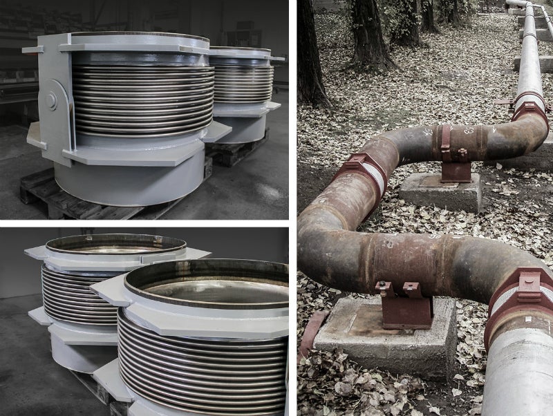
This power plant is the largest of its kind in Africa and its state-of-the-art design ensures a highly efficient utilisation of steam. The expansion joints were installed in this steam system, near the steam turbines.
The selection of corner relief expansion joints
Corner relief expansion joints were selected as the optimal solution for this project. Turbines in general do not withstand loads.
Turbines often operate under high pressure and in high temperature conditions, resulting in high pressure thrust forces being transmitted to the connection ends of the turbine.
By installing a pressure balanced expansion joint, like a corner relief expansion joint, the loads acting on the turbine and its connecting pieces (flanges and welding ends) can be relieved with the loads then being maintained at an acceptably low level.
Corner relief expansion joints in general
Corner relief expansion joints can be designed for the absorption of axial and lateral movement.
The balancing bellow is connected to the pipe system through the tie rods with the balancing bellow extending when the flow bellow is compressed axially. The system therefore goes by the name ‘constant volume system’.
The pressure reaction force is absorbed as a pulling force in the tie rods and the section between the tie rods, which includes the corner, is thus free to move axially with the spring force of the bellows acting as the only load on the pipeline.
Due to the design, the load acting on the pipeline/connected parts is the sum of the spring stiffness of the balancing bellow and the flow bellow.
Corner relief expansion joints reduces loads
Due to the loads transferred to the pipe system and / or the connected equipment like the turbines and because the pressure reaction force can reach a considerable size, high demands are placed on the dimensioning of the guides and anchors used for supporting the pipe system.
By installing a pressure balanced compensator the pressure reaction force is balanced internally in the expansion joint and only the force needed to move the compensator is transmitted to the pipe system.
This type of expansion joint reduces the loads that act on the guides/anchors significantly, meaning that the number of guides / anchors can be reduced and/or that they can be installed in a lighter version. This will usually result in considerable cost savings.
Full traceability
Full traceability was required for these expansion joints and therefore all necessary tests were made with full documentation following the delivery.
Data on the expansion joints
Dimension: DN 250 – Installation length: 1000 mm – Medium: Steam – Design temperature: 218°C – Design pressure: 21,5 barG – AX: +/-12 mm – LA: +/- 5 mm – Bellow: 1.4571 – Welding ends: API 5L Gr. B – Flanges: 1.0425 – Inner sleeve: 1.0425